Tuesday, July 29, 2008

My 6M Junkbox Tuner

Shopping in the local emporium found me face to face with a Tokyo Hy-Power HL602V 6M amp which is their 200 watts beast. I had been considering one of these for a while to complement my FT-950 which I use on 6m. Knowing how long they take to arrive when ordered, the quality, and also that the price was only going to increase I decide to buy it.

Having got it home (And smuggled it past the XYL) I installed it and tested it into a load.

Having spent so much on the amp I was concerned about running it into a bad VSWR. My HB9CV would easily take the power but was presenting the amp with about 1.5:1 which is quite a few watts of reflected power when running 200 watts. What I needed was a tuner to protect my investment.

I had seen a couple of designs on the net so I decided to have a go and build my own. The design used two variable capacitors and an inductor in a pi network. But the designs I saw tended to use plastic enclosures to avoid interaction with the coil.

As I was going to run 200 watts I decided a metal enclosure would be safer and more stable. To avoid interaction the sides of the box would need to be 3.5 times the diameter of the coil from the coil.

So I needed a fairly large enclosure for this project. The most suitable product I found is provided by Maplin Electronics. Their enclosure AB15 is 202mm in length, 152mm deep and 76mm tall.

http://www.maplin.co.uk/Module.aspx?ModuleNo=1728&criteria=enclosure&doy=29m7#Faq

The last two figures were the most important. The coil would only be 3x the diameter of the coil from the top and bottom of the box but I felt this would be okay.

Aluminum has to be the easiest metal to work with and 20 minutes had all the holes drilled and punched ready for all the components.

The tuner didn’t have to match a very broad range so the coil is 3 turns of 2.5mm copper wire at ¾”diameter

I had a couple of variable capacitors in my junk box which were about 50pf. I made sure the capacitors were properly secured to the chassis and all the joints soldered. You can see that I suspended the coil from the wires between the coaxial sockets and the capacitors so it was in the middle of the box (Away from the sides). This also makes it easy to remove and adjust or replace the coil.

Initial testing on low power went well; the tuner easily matched the antenna. I screwed the box closed, re-tuned and everything worked fine running 100 watts. I increased the power while carefully watching the reflected power. The unit needed a small re-tune but everything still seemed fine.

On the air I went back to an EA calling on SSB from southern Spain. The band was closing and he was just about readable but gave me a 59 in return so the amp and tuner were doing their thing.

This tuner handles plenty of power and although it has a limited range I could tune my G5RV jr with it!
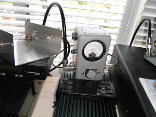
The ATU needs some cosmetic finishing + knobs but it will do for now… I can beautify it when the sporadic e season ends!

Wednesday, July 23, 2008

6M Swiss Style?

With only a sloop I thought it about time to put up a reasonable antenna for the 6M band. About a year ago I bought a 6M HB9CV which I had left in the garage until I felt ready to tackle it.

This was a second hand antenna and I have no idea who originally manufactured it. Initial inspection revealed that all the parts were there so I put it together on the garden table to see how it looked.

Apart from an end cap for one of the elements it looked okay. I noticed the matching section is kept away from the boom and elements by a set of grommets. That’s quite a neat idea as keeping the matching section the correct and even distance from the elements and boom is one of the common issues with this antenna and the idea appeared to work okay.

The antenna is driven through a variable capacitor and I was concerned that the one supplied with the antenna was a bit wimpy. Short term it needed to handle 100 watts pep & 40Watts on RTTY.

But I’m considering running a couple of hundred watts RTTY in the future and could already see the cap disintegrating in a molten glob ruining the antenna. As I had some ptfe coax left over from the trap project I decided this would make a useful capacitor.

I adjusted the existing capacitor for minimum SWR and then measured it on the MFJ analyser. It came up at 36pf so I cut an appropriate length of coax and trimmed it to the same capacitance.

Its worth trimming off about 3mm of screen at the far end so ensure the home-brew capacitor won’t flash over (I imagine this capacitor will need to work at quite a high voltage when running a few hundred watts through it!).

The finished coax capacitor was curled up and fitted to the antenna feed point. When complete the SWR was about 1.4:1 which was about as low as I could get it in my back garden. I have an ATU in the transceiver and it was capable of tuning that out so I decided not to fiddle further. Also experience has told me that you can adjust all day only to find things change once the antenna is installed.

The antenna is mounted below a small 2m beam on the back of my dormer window. It clears the rooftop and I can turn it using the Armstrong method. The other advantage of this set up is that there are no ladders to climb. All I did was assemble the antenna reach out and fix it in position.

I usually leave it pointing south east towards Easter Europe but I only have to reach out and I can rotate it towards W-land or wherever the DX is coming from. I can see a big improvement compared to the sloop with 59+20 signals form Italy and Hungary. The SWR is below 1.4:1 between 50.0 – 50.3 mhz so the rigs internal tuner easily takes care of it, most importantly testing it with 100watt carrier it appears quite stable. I’m sure this antenna can easily handle full legal, I wonder if the neighbours can?

Monday, July 21, 2008

Fire!

Well its been an interesting summer (Not that we have had much sun yet) conditions on the HF bands have been poor but its motivated me to make some improvements to the new antenna farm.

I finally constructed a trap for 80m out of RG58 and extended my inverted V for top band. This should have been simple but I noticed that the trap tended to drift during transmit. I’m not sure if the coax was warming up or what but its very annoying as my auto ATU could start to re-tune half way through a QSO. The top of the vertical was very hot & experiencing very high voltages.

I decided to replace the trap with a simple coil and capacitor. I also tuned the trap away from resonance to cool things off. Being the skin flint I am I thought that I would build the 100pf capacitor out of coax.

Well that worked well and was very stable for about 2 minutes at which point I exceeded the breakdown voltage of the coax and it burst into flames! It was in the air so apart from the coil former no damage was done.

I tried again but used a 100pf doorknob capacitor with low drift... it cost me a bit but still drifted >:-(

I had a re-think and decided to have another go building a coaxial trap. This time I used RG412 PTFE coax and a larger 2.5” coil former. RG412 coax is the same dimensions as RG58 so easy to wind into a coil but its not cheap.


Success! The trap was tuned to 3.8Mhz and there is no drift running full legal (400 watts in the UK). Now I have Top Band as well as 80m. You can find me on 1.84Mhz or 3.85Mhz RTTY